 s




SWITCH-MODE
RECTIFIERS
| Image | Description | Part Number | PDF File |
|---|---|---|---|
| Module Control Card - CTRD02 | |||
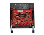 | Module Control Card - CTRD02 Wide current / voltage regulation range: Fast feedback loop and fully differential output feedback Min Pulse Control down to 0.2 micro seconds allows to improve load regulation Active Blanking of Pulse to control medium and high voltage applications and improve regulation in low voltage Slope Compensation to improve output stability and ripple Improved Immunity from: Protection of FAN (overcurrent and short circuit) by a Mosfet circuit instead of fuse Improved reliability with Tantalum free capacitors Standard on pulse (PP) and pulse reverse (PPR) rectifiers and over 200vdc rectifiers Recommended for voltage controlled processes | CTRD02 |  |
| 4 Line Display | |||
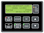 | 1st line: Firmware name and release 2nd line: Actual Volt, ampere 3rd line: Ampere meters in A/hour or A/minute 4th line: Thermal alarm, errors. | OPP002 |  |
| Water Flow Sensor and Solenoid | |||
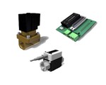 | Water Flow Sensor and Solenoid Water cooled rectifier optional for low water flow rate alarm Features: Benefits: Flow Sensor and Solenoid are placed outside the rectifier for an easy assistance and not connected to the rectifier at the time of shipping. Wiring and Interface Board (protected by metal box) are already installed on the rectifier. Main components: It is used for powering the solenoid and handling the flow sensor signal for low water flow rate alarm. This board is connected to the 25pin D-sub connector of CPU through the corresponding female connector on PCB. On the board, screw connectors CN1/CN2 can be used for RS485 network (with termination, pull-up and pull-down resistors activable by dip switch). Solenoid FSN: 8630-40-001(Brand: SMC | P/N: VXZ242FGA): servo-solenoid, 24VDC, 7W (low power consumption), NC, G 1/2" , brass body. Flow Sensors FSN: 8630-40-007(Brand: IFM | P/N: SV4200): with integrated display, range 1 to 20L/min., G 1/2" , 24Vdc, PNP FSN: 8630-40-006 (Brand: IFM | P/N: SV5200): with integrated display, range 2 to 40L/min., G 1/2" , 24Vdc, PNP Available only on Q500 rectifiers, single tower or multitower system. Compatible with Profibus-DP, Devicenet, Profinet and Ethernet/IP communication adapters. Not compatible with Analogue Interface (ANL002). Flow Sensor and Solenoid can be sold together or separately. | WFS20A WFS40A |  |
| Analogue Cards | |||
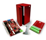 | The ANL card is a microprocessor driven electronic card which is to be connected to the RS232 serial port of the rectifier's CPU card. Available for DC and DCR machines only. It is able to accomplish all the following operations: 6 DIGITAL INPUTS - from 24Vdc contacts Start/Stop selection. Configuration of 1 or 2 potentiometers for simultaneous manual control of current and voltage. Driving mode selection: current or voltage. Used only if a potentiometer is configured. Preset function push-button. While rectifier is stopped, it allows to pre-setting on an external amperemeter and voltmeter the desired value of the current and/or voltage before actually starting the rectifier. Direct/Reverse polarity selection (Only for DCR machines). Available for future options. 6 DIGITAL OUTPUTS - Solid-state relays (TLP523-4) Start/Stop indication. Rectifier status indication. Direct/Reverse polarity indication (Only for DCR and PPR machines) Driving mode indication: current or voltage. Dosing pump activation. This output is activated for a pre-defined time when the rectifier's TOTAL A/h meter exceeds a pre-defined limit value. Pump activation time and A/h threshold value must be configured on the rectifier's operator panel. Available for future options. 2 ANALOGUE INPUTS For current and voltage regulation. Inputs are either from manual potentiometers or from PLC analogue signals. Potentiometer’s value must be between 10kΩ and 22kΩ.2 ANALOGUE OUTPUTS For current and voltage readings. | ||
| Communication Adapter | |||
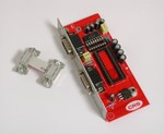 | Communication adapter | PFB001 | |
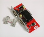 | Communication adapter with PROFIBUS-DP | PFB002 | |
| Communication adapter with PROFINET | PFN002 | ||
| Communication adapter with ETHERNET IP | PFN003 | ||
| Communication adapter with DEVICENET | DVN002 | ||
| REMC - Remote Control & Master-REM | |||
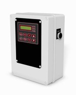 | The remote control unit is an electronic device that communicates with the Quasar rectifiers via serial bus. It is optional for single tower rectifiers (REMC) and necessary for multitower systems (Master-REMC). It is available in many configurations with different power supplies, displays, optional inputs, isolated analog channels and communication protocols. DISPLAY OPTIONAL INPUTS - Start/Stop selection - Manual/Automatic operation mode selection - Direct/Reverse polarity selection - Current/Voltage regulation mode selection - Current or voltage adjustments RESET BUTTON POWER SUPPLPY 3 ANALOGIC I/O 0-10V - opto-isolator for Analogic I/O 0-10V and converter for 4-20mA (3 channels) DB25 OR INTERNAL DIN RAIL MULTI-TOWER INTERCONNECTION (Master-REMC) Opto-isolated voltage feedback input Communication adapters (optional) Serial bus for Modbus-RTU / ASCII (optional) | ||
| For RS485 Network | |||
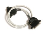 | Assembled RS485 Comm Cable D-Shell 25 pin to D-Shell 25 pin w/ 380 Ohm bias resistor. | CB485G | |
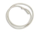 | Add: How many meters req of RS485 cable (3*AWG22) | 8220-80-010 | |
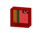 | Input/Output screw terminal for RS485 network (Q100) | IOS001 | |
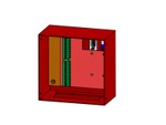 | Input/Output screw terminal for RS485 network (Q500) | IOS002 | |
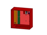 | Input/Output screw terminal for RS485 network (Q300) | IOS003 | |
| Programming Cable for Flashing CPU/REM | |||
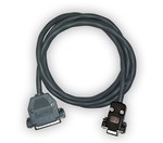 | It is needed to flash inside CPU or REM a new firmware that has been released to add new capabilities, or in case a new configuration is needed (like adding a new communication interface). The flashing cable is connected on one side to a RS232 port on the PC, and on the other side to the DB25 connector available on the CPU or REM boards. Length: 1.5m | CBFL01 | |